Any modern electromechanical equipment is equipped with special devices that regulate its operation and protect against overloads. In refrigerators of any manufacturers, such a device is a start-up relay. An important role in refrigeration units is played by a thermal relay. Its malfunction can lead to improper cooling and loss of equipment performance.
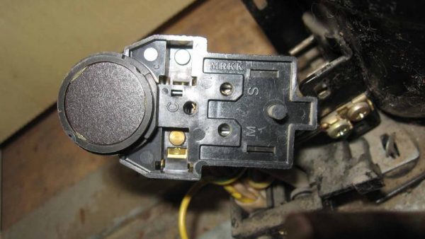
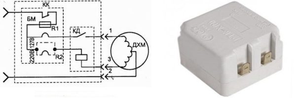
Start protection relay - top view
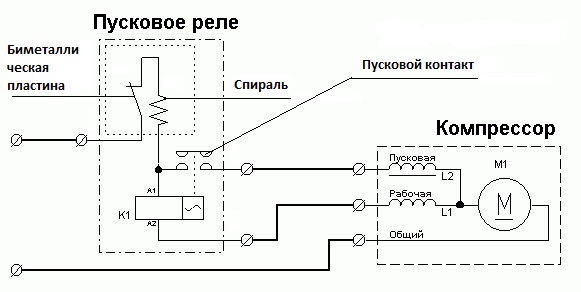
Start relay connection diagram
This device is necessary to start a single-phase asynchronous compressor motor. The motor stator includes two windings - starting and working. The first serves only to create a starting torque and start the compressor. The second winding is needed to maintain the rotor in working condition by continuously supplying alternating current to it.
Important! To regulate the process of supplying and turning off the power to the starting, working winding of the electric motor, as well as for the overload protection function, a start-up relay is provided.
Induction circuit
The relay connection scheme is not complicated. The input of the device is supplied conditionally “zero” and “phase”, and the output “phase” is divided into two lines. The first line connects to the working winding of the electric motor, and the second approaches the starting winding through the starting contact.
In the relay of old and modern refrigerators, current is supplied to the working winding through a spring with a high resistance, and then through a connection with a bimetallic jumper. With a strong increase in current in the circuit (motor jamming, short circuit between turns and other breakdowns), the spring heats in contact with the jumper, which changes shape under the influence of temperature, thereby breaking the contact and disconnecting the compressor.
Induction Circuit
In this scheme, to start the electric motor, a coil (K1) is used, which is connected in series with a working winding. A voltage supply with a stationary rotor of the engine provokes an increase in the current on the coil with the formation of a magnetic field attracting a movable core, which closes the starting contact. After gaining speed by the rotor, the current in the circuit decreases, the magnetic field in the solenoid decreases, the starting contact opens by gravity or by a compensating spring.
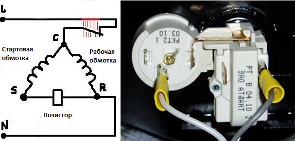
Posistor switching mechanism
In modern household refrigerators, a start-up relay with an integrated posistor is used (a resistor that increases resistance with increasing temperature). The circuit of this device (Fig. 2) is similar to an induction relay, but instead of a coil, a posistor connected to the start circuit is used to close and open the start contact.
When power is applied to the compressor, the temperature of the resistor is small and it passes current to the starting winding. Since the resistor initially has resistance, it heats up and opens the motor starting winding circuit. The cycle is repeated after the thermal relay is triggered and the refrigerator is turned on again.
Posistor switching mechanism
Thermal relay circuit
The temperature regulator in the refrigeration unit plays the role of a device that supports operation in a given temperature mode by periodically turning the compressor on and off.At the present stage, 2 types of thermal relay are used:
- Mechanical devices are used in old refrigerators, as well as in modern manufacturers such as Indesit, Stinol, Atlant.
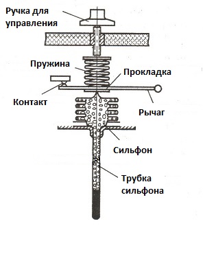
Scheme of a mechanical temperature controller
This device is a gauge type. The bellows and its tube (a sealed corrugated metal container) are filled with freon or chloromethyl, which is in the form of steam. The pressure of the working medium directly proportionally changes with temperature. At the end of the tube, freon is in a liquid state and is pressed against the evaporator.
With an increase in temperature, the pressure of the bellows on the spring increases, the lever works, the contact closes. When the temperature decreases, everything happens the other way around. The contact opening mode depends on the spring force, which is regulated by the control knob.
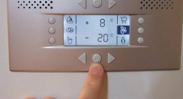
- Electronic thermostats are used in refrigerators of such manufacturers as Samsung, Beko, LG.
Mechanical thermostats in their work rely on the temperature in the evaporator, and electronic counterparts - on the air temperature in the chamber. A positive aspect of electronic models is the ability to display temperature (that is, a person can visually evaluate the operation of the thermostat) and a smaller error.
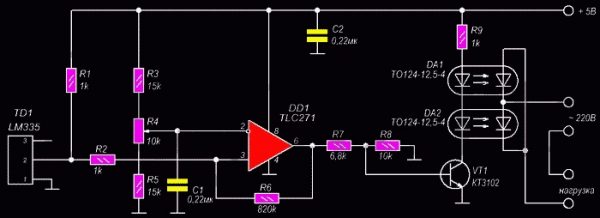
Electronic Thermostat Diagram
The temperature controller in this circuit is the LM335 temperature sensor. The device is a zener diode sensitive to temperature changes. The climate in the refrigerator chamber is regulated by a variable resistance R4. As the air temperature rises, a signal appears at the output of the TLC271 comparator, opening the KT3102 transistor, which starts the refrigerator. Accordingly, when the temperature decreases, zero appears at the output of the comparator, the compressor turns off.
Checking the refrigerator relay for operation
If the refrigeration unit does not turn on or if it is turned on irregularly, then most likely it is a start relay. The cause of its malfunction may be:
- Oxidation or burning of contacts.
- Mechanical damage.
- Overheating of the posistor element.
- Violation of the relay mounting, leading to its incorrect location.
- Burnout spiral.
- Jamming of the core.
No need to rush to buy a new refrigerator relay, it is better to learn how to check it, and try to do it.
In the induction mechanism, a solenoid is pulled out, contacts are checked, during oxidation, they are cleaned with sandpaper. The core may be broken, then it needs to be replaced. Wipe the surfaces in contact with alcohol. Check the integrity of all elements. It must be remembered that relays of this type are installed strictly in a certain direction indicated by the arrow. After the above actions, we connect the relay to the compressor and turn on the refrigerator. If the engine does not work, then most likely a compressor breakdown.
Verification of RTP-1 and RTK-X devices
To check, put the relay in the correct position (up arrow) and ring the contacts 1 and 3 with a multimeter.
RTK-X device diagram
If the contacts ring, then the relay is working. In these models, visual inspection is desirable, as shorting may occur through the plate of the contact holder.
Testing DXR and LS-08B devices
DXR should be put with the bar with the terminals up and a multimeter to check the integrity between 1 and 3 or 1 and 4.
Position LS-08B with the inside up, ring between 2 and all terminals or between 3 and all terminals. Where the contacts do not ring, look for a malfunction.
Check thermal relay
If your the refrigerator does not turn off for a long timeIf it constantly works or does not turn on at all, then the thermostat may be to blame. The culprit must be dismantled, and a jumper should be placed on the remaining contacts. If the refrigerator turns on, then check the thermostat itself. It is placed in a container with cold water, and the outputs are called by the tester or the resistance at the outlet is measured.
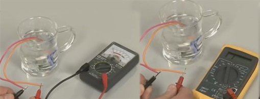
Contact tester
In the absence of a sound signal or in the presence of resistance, the thermal relay is faulty, it must be replaced.