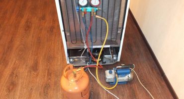
The operation scheme of a conventional compressor-type refrigerator is as follows:
- The compressor, driven by the engine, draws in the gaseous coolant from the evaporator. The coolant is compressed, heated and gets into the condenser.
- There it cools to normal temperature and liquefies.
- Then the coolant enters the evaporator, where it evaporates, cooling the walls of the heat exchanger, the cooling chamber.
- From the evaporator, the coolant again enters the compressor.
- The compressor motor is connected to the circuit through a thermostat. After cooling the refrigerator compartment to the set temperature, it opens the contacts and turns off the motor.
- Over time, the compartment temperature rises, the thermostat again connects the engine through the start relay.
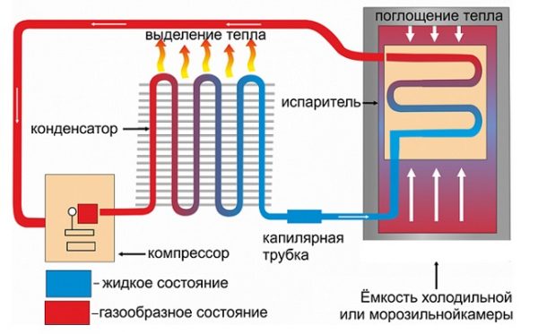
The scheme of action of the refrigeration unit
Electrical equipment includes:
- compressor electric motor;
- lighting elements;
- heaters in absorption type systems;
- fans for forced air exchange.
Elements of automation systems include:
- Thermoregulation devices in refrigeration compartments. They can be either mechanical or electronic.
- Start protection relays. They are used to facilitate the starting of asynchronous compressor motors and their automatic shutdown in case of overload.
- Systems for removing frost from the surface of the evaporator.
- Integrated automatic control systems that perform all these functions, plus control over the shelf life of stored products and replenish their stocks using an electronic order.
The electric circuit of the refrigerator and the principle of its operation
After connecting the device to the power supply, the current flows through the contact group of the thermostat, the protective relay, the inductive coil of the starting relay and the main winding of the electric motor.
While the rotor is stationary, the current is significantly greater than usual. After the start relay is activated, the inductance winding is connected to the circuit. The armature rotates, the current decreases, the relay opens, and the electric motor operates in normal mode.
After cooling the chamber to the required temperature in the refrigerator, the thermal relay trips and breaks the power supply circuit of the electric motor. The temperature in the compartment begins to rise, and when it exceeds the set value, the engine is connected again. The main duty cycle is repeated.
The protective relay responds to the current flowing in its circuit. If the motor is overloaded, the current in its circuit rises. When it reaches the limit value, the protective relay breaks the circuit. After the engine and relay have cooled, it closes the circuit again, starting the engine. The system protects the engine from premature wear, and the room from fire. The sensor in the relay is a bimetallic plate welded from metal strips with different coefficients of thermal expansion. When heated, the plate changes its shape, bends and breaks the chain. After cooling the plate, it takes the initial head start, closing the contacts of the circuit.
Below is a diagram of a Stinol compression refrigerator.
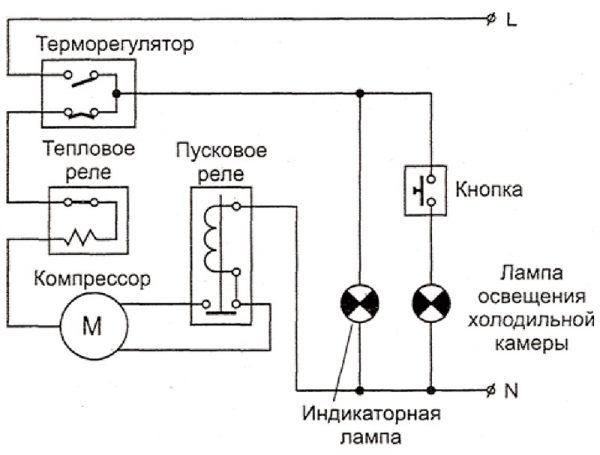
Electrical circuit of the compression refrigerator
Refrigeration unit integration diagram
When designing the interiors of a modern kitchen, it is necessary to solve the problem of combining a variety of shapes and colors of kitchen appliances:
- slabs;
- oven;
- a refrigerator;
- microwave oven;
- a dishwasher;
- hoods, etc.
A popular solution is to use fully integrated kitchen appliances. In this case, it is hidden inside modular cabinets and shelves of standard sizes with front panels decorated in the same style.
To this end, manufacturers produce special lines of equipment designed for installation in kitchen modules.
The walls and doors of this technique are not painted with enamel, since they will be hidden inside the cabinets, the doors are equipped with special systems for attaching hinged panels.
Each manufacturer in the user manual must provide an embedment scheme,
which specifies the dimensions of suitable modules, the minimum depth, width and height of the opening, the distance from the evaporator to the rear wall of the cabinet, the size and location of the holes to ensure natural air circulation.
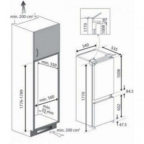
Built-in Scheme
There is also a partial embedment scheme. In this case, use the usual model of the device with a painted door. The refrigerator is mounted in a niche open in the front in the kitchen furniture. Air exchange requirements, however, must be met
Refrigerator Connection Diagram
The refrigerator is connected to the mains by simply plugging the plug into an outlet.
However, a number of requirements must be observed:
- The wiring must be fully operational, they will allow the connection of another device according to their technical characteristics.
- The socket must be held tightly in the wall, the cable fastening should be tightened. If the outlet sparks or heats up during the operation of the refrigerator, it should be replaced, and the wiring from the outlet to the distribution panel should be checked.
- It is not recommended to connect the device through extension cords or splitters. It is more reliable to equip a separate outlet.
- Wiring and socket must be earthed.
In addition to the requirements for the electrical network, there are a number of general recommendations for the placement and connection of the device:
- The device is placed as far as possible from the window to avoid its heating by sunlight.
- The device should not be placed near heat sources: stove, oven, heating radiator, on a heated floor.
- The refrigerator must not block the passage with an open door.
Compliance with these recommendations will make the operation of the refrigerator convenient, safe and economical.
Absorption refrigerator: scheme
In addition to the usual compression-type household refrigerators, units based on the absorption effect are quite widespread. They have no moving units and elements; the natural circulation of the coolant is carried out. A liquid with a low boiling point is used in its quality. It should be readily soluble in a liquid with a high boiling point, called an adsorber.
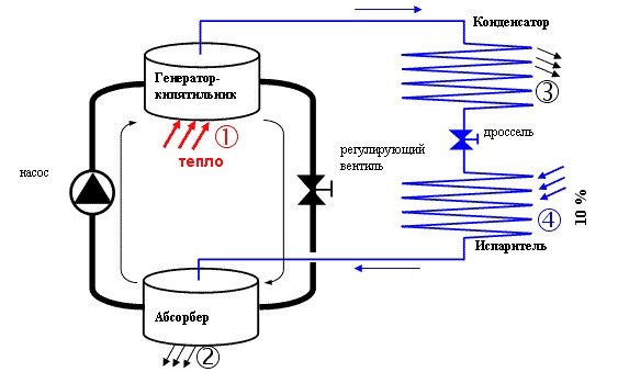
Absorption device circuit
The concentrated coolant is located in the tank (2), from which it enters the heat pump, made in the form of a copper tube heated by an electric heater, and then to the steam generator (1), also heated by electricity. The coolant evaporates and mixes with adsorber vapor. The gas mixture enters from the condenser - reflux condenser (3), in which the fractions of the mixture are separated. The adsorbing liquid is liquefied and returned to the generator, and the coolant in the form of gas flows by gravity to the evaporator. During evaporation, a large amount of energy is absorbed, and the temperature drops significantly. Next, the coolant returns to the container with the adsorber and is absorbed by it. The cycle repeats.
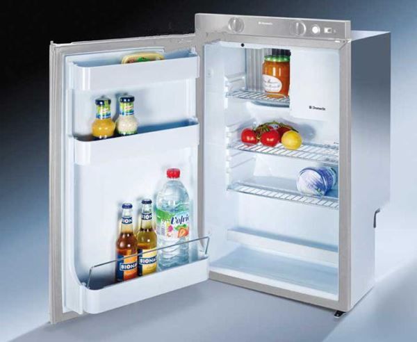
Absorption type built-in apparatus
Such units are characterized by a long service life and low noise. They can tolerate long shutdown periods without the risk of refrigerant leakage.
The disadvantage is high (50% higher than that of compression) power consumption.
Such systems are readily used in places of seasonal residence.
Scheme of the refrigerator on Peltier elements
In devices of this type there is no refrigerant, which makes them indispensable for travel. The cooling of the chamber is achieved due to the Peltier effect. Heterogeneous semiconductor elements soldered together are heated on the one hand and serve as a cooler on the other. With this device, you can cool the camera to -50about FROM.
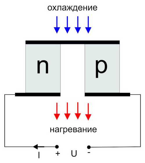
Scheme of the Peltier element
The advantages of the circuit is the exceptional simplicity and low cost of the device. It is enough with a fan to cool “the hot side of the semiconductor element, and“ integrate the “cold side” into the lid of the refrigerator compartment — the cold air itself will go down.
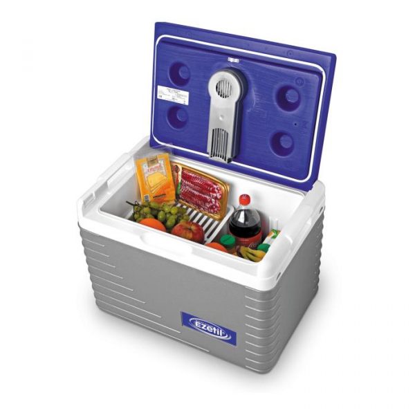
Peltier-based car refrigerator
The indisputable advantage of the circuit is insensitivity to shaking and vibration, small dimensions and the ability to quickly defrost products by simply switching the polarity of the Peltier element.
The disadvantage is the high power consumption and low resource of the semiconductor element.
Relay and thermostat diagram
Relays and thermostats are the most common occurrences that occur when using the refrigerator. Repairing them or replacing it is quite within the power of a home master who knows how to handle a screwdriver and a tester. In modern refrigerators, manufacturers are increasingly taking a course on the use of non-repairable units to be replaced entirely.
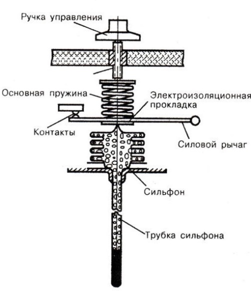
Thermostat diagram
The thermostat is used to maintain the set temperature in the refrigerator or freezer. The capillary tube of the bellows is filled with a substance that changes its volume under the influence of temperature. As a result of this, the axial movement of the moving part of the device occurs, while the power lever is deflected and the contacts controlling the thermal relay are closed (or open).
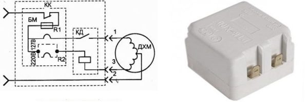
Scheme of the thermal relay of the Stinol refrigerator
When the temperature rises above the set value, the contacts close, current flows through the control winding of the relay, the start relay is activated, and the compressor electric motor starts.
By cooling measures, the bellows tube contracts and breaks the control circuit of the relay. The compressor motor is shutting down. After turning off the motor, the temperature in the chamber begins to rise gradually until the thermal relay trips. The cycle repeats.